Architecture#
Overview#

Télega is a firmware that runs high-end electric motor controllers and motor control modules developed by Zubax Robotics. It is designed for use in propulsion drives in electric aviation and other applications where exceptional energy efficiency, reliability, and predictability are required.
Internally, Telega is not involved in motor control, as this is delegated to Zubax Dýshlo — a platform-agnostic, highly abstract AUTOSAR-C++14-compliant software library designed for use in high-integrity hard real-time embedded systems devoted to electric motor control. As the motor control software is the most complex part of an electric drivetrain, Dyshlo is the most critical and intricate component of a motor controller. Dyshlo is available as a separate product when a deeply customized motor control solution is required; please reach out to Zubax Robotics for details.
The function of Telega is to serve as a glue logic, accepting commands through external communication interfaces, passing them over to the Dyshlo motor control core for acting upon, and providing the interface between the hardware platform and the Dyshlo core. Telega runs as a low-level, baremetal process without an operating system nor middleware; this design was chosen to reduce the state space to the bare minimum and thus minimize the risks of unintended behaviors emerging in the system.
Telega can accept commands via two families of external communication interfaces:
Cyphal — an open protocol for real-time intravehicular distributed computing and communication based on modern networking standards[1]. The Cyphal interfaces accept commands of different modes (torque, velocity, voltage control, etc.) and publish diagnostic data (power, torque, velocity, error/warning states, etc.). In certain Telega-based products, there are redundant interfaces for enhanced fault-tolerance.
Auxiliary port — a multi-purpose GPIO/analog port that supports a variety of simple low-level communication options:
RC PWM input supporting refresh rates from 40 Hz to over 500 Hz.
Simple analog voltage control suitable for testing, e-mobility, and similar applications.
Motor temperature sensor (thermistor) connection.
All of the available interfaces are covered in detail in the Interfaces chapter.
Hardware types#
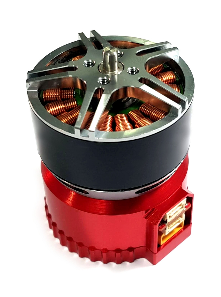
Broadly speaking, Zubax Robotics offers three types of Telega-based products: motor controllers, integrated drives, and motor control modules.
An integrated drive incorporates the entire solution for converting electrical power into mechanical power, providing a DC power input on one side and the motor shaft on the other side. In this tightly integrated configuration, the motor controller is aware of the type and characteristics of the motor, the power electronics, motor sensors, etc. Therefore, no sophisticated tuning is required.
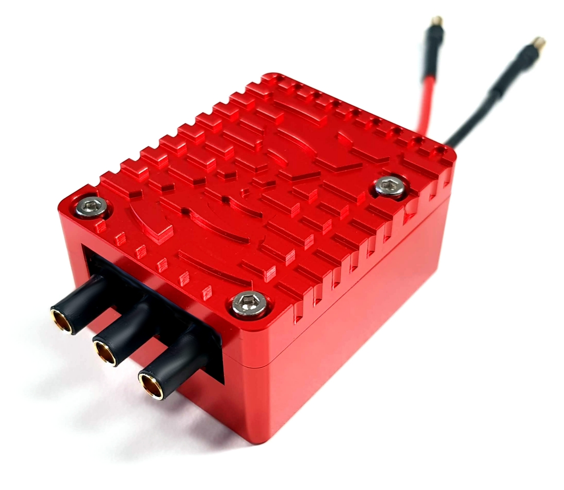
A motor controller accepts DC power and delivers it to an arbitrary user-selected motor connected to the phase wires of the controller, with optional rotor position sensors, motor temperature sensor, etc. The user is responsible for tuning the motor controller for optimal performance with the chosen motor. Zubax Robotics provides a professional tuning service where the customer can ship the propulsion system (electric motor or the entire power train, depending on the application) to the lab for full characterization and tuning.
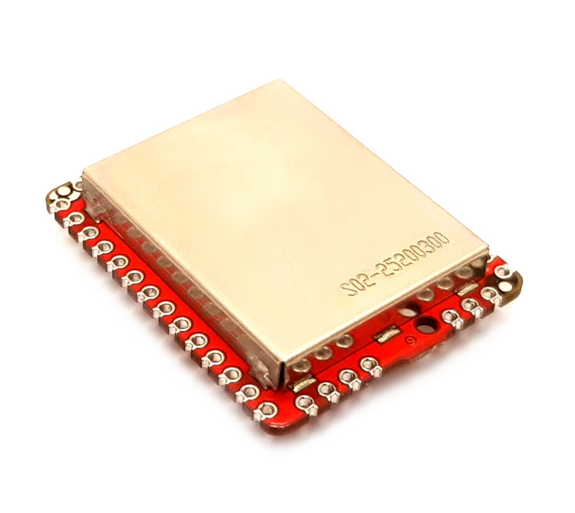
A motor control module is the essence of an electric drive extracted into an easy-to-reuse integrated module incorporating the motor control software and the microcontroller that executes it along with some auxiliary electronics. Motor control modules address most of the complexity associated with designing a custom electric drive.

Motor control module architecture.#
As Telega needs to be aware of certain properties of the power stage connected to the motor control module, certain configuration parameters need to be set correctly before the motor control module can operate the custom controller. This is covered in detail in the Voltage source inverter (VSI) interface section.
Zubax Robotics provides a consulting service allowing the customer to fast-track the development of a custom electric motor drive based on one of our integrated motor control modules.
High-level state machine#
Once a Telega-equipped device is powered up, the embedded bootloader is launched, which verifies the integrity of the firmware with a strong 64-bit CRC, performs other integrity checks, and launches Telega in case of success.
The initialization state involves the configuration of the hardware and the retrieval of the configuration parameters from the non-volatile memory. As Telega is a high-integrity hard real-time system, any activities not directly related to the main function — which is motor control — are purposefully avoided during normal operation. As such, Telega can only access the non-volatile memory during the initialization and shutdown (restart).
The operational state is the normal operating state where the main functionality of the device is implemented. This state has several sub-states described in the Commands chapter. In this state, the normal operation of the device cannot be influenced by the state of auxiliary subsystems such as the non-volatile memory, since none are accessed.
The uninitialized state is entered upon unsuccessful initialization, which may happen if the critical configuration parameters are missing (such as the VSI parameters). In this state, the device cannot operate normally (the motor cannot be started), but it is accessible over the network for reconfiguration. A restart is required to leave the uninitialized state.
The device remains in the operational or uninitialized state until powered off (by physically disconnecting the power supply) or a restart command is received. In the latter case, before actually restarting the system, the shutdown state is entered which transfers the modified configuration parameters (if any) to the non-volatile memory. It follows that in order to retain configuration changes, it is necessary to send an explicit restart request to the device, otherwise, the changes will be lost. If no restart requests are issued, Telega will not attempt to alter the state of the non-volatile memory, which is an important guarantee for high-assurance systems.
A special panic state is entered upon an unrecoverable error occurring at any moment in any other state. The panic state performs the emergency deactivation procedure (such as powering off the power electronics and putting it into a safe state) and then waits for up to approximately 10 seconds before restarting the device. Normally, this state is never activated during the entire lifetime of the device, except in the case of a physical hardware problem (e.g., chip malfunction, strong electromagnetic interference), a software defect, or a grossly incorrect device configuration[2].
Telega high-level state machine#
The current state is indicated via the status indication LED, the system status register, and other interfaces.
System tick#
In Telega, there are two classes of activities that differ in their time-criticality:
Hard real-time computation related to the motor control.
Soft real-time computation related to servicing the networking stack, interfaces, state machine, and self-diagnostics.
Telega manages the soft real-time activities using a deterministic EDF scheduler. When the scheduler is idle, the core is put into the sleep mode to reduce energy consumption.
The hard real-time activities pertaining to motor control are scheduled by a hardware timer and executed in the interrupt context, which preempts the EDF scheduler and is the only interrupt implemented in the system. The worst-case interrupt latency is guaranteed to not exceed 1.5 microseconds. Said interrupt is referred to as the system tick.
Normally, the integrator should not attempt to increase the maximum system tick frequency unless advised by Zubax Robotics, as it may cause the EDF scheduler to experience CPU starvation, which may potentially lead to disruptions in the networking stack. The reduction of the system tick frequency, on the other hand, does not incur such risks.
Registers#
Telega provides access to its configuration parameters and diagnostic information via Cyphal registers[3]. Per the Cyphal specification, there are four kinds of registers: mutable/immutable \(\times\) persistent/volatile. Configuration parameters are mapped to mutable persistent registers.
The registers are split into several categories which are distinguished by the name prefix.
For example, those pertaining to the motor model are named starting with motor.,
those related to the VSI driver are named starting with vsi., and so on.
Certain registers only apply to a particular command, which is reflected in the name prefix.
Mutable persistent registers that affect the operation of the device may take effect either at the next command execution or after restart. By default, one should assume the latter unless documented otherwise. Remember that configuration parameters (i.e., mutable persistent registers) are not committed to the non-volatile memory until the device is commanded to restart.
This reference manual purposefully omits the description of some registers. These are not intended for production use and should not be relied upon; their name, type, contents, and semantics may change arbitrarily between minor releases with no regard for compatibility.
System status register#
The system status register sys.status contains details on the operational state in JSON format.
It is empty in the uninitialized state.
This register can be evaluated in shell scripts with the help of
Yakut and jq; e.g.:
1y r 125 sys.status | jq fromjson
The schema of the JSON-encoded value specified below. Additional keys may be introduced at any level for extended information, but they should not be relied on. The detailed schema is further specified separately per command.
{COMMAND_NAME: COMMAND_VALUE}
Where COMMAND_NAME is the lowercase name of the current command (e.g. drive),
and the COMMAND_VALUE is command-specific (may be null).
System debugging enablement register#
The system debugging enablement register sys.debug should be always set to false,
unless explicitly advised otherwise by Zubax Robotics.
Factory reset behavior configuration register#
The factory default configuration reflects the known fixed characteristics of the product.
The factory default configuration of a motor control module is minimal, as most settings are dependent on the hardware design the module is integrated into, and therefore they have to be provided by the user.
The factory default configuration of an integrated drive is extensive, as the properties of the inverter as well as the motor (and sometimes the load) are known.
The correct factory reset behavior that takes into account the above considerations is configured via the
sys.golden register,
which contains a list of space-separated register name prefixes whose values are retained
(not reset) across a factory reset.
For example, sys. vsi..
Upon delivery, devices of different kinds will have the sys.golden register configured differently.
It is recommended to avoid altering this register to avoid accidental loss of the correct factory configuration
when a factory reset is performed.
Embedded bootloader#
Telega supports in-field software update via Cyphal or DroneCAN[4] with the help of the embedded bootloader based on Zubax Kocherga (please refer to the Kocherga documentation for an in-depth discussion of the bootloader’s capabilities). A detailed description of the Cyphal software update service is available in the Cyphal Specification.
The bootloader is compatible not only with the present version of Telega, but also with the early Telega v0 that implements DroneCAN instead of Cyphal. The compatibility of the bootloader with both protocols is therefore essential to allow the user to switch between the two generations of the Telega firmware. A device running Telega v0 can be upgraded to Telega v1 with the help of the Yukon GUI tool.
Warning
The bootloader does not support redundant network interfaces.
Telega-based products that are equipped with redundant network interfaces can only perform an in-field software update if the primary interface within a redundant group is connected to the network and is operational. For example, a device equipped with a doubly-redundant CAN interface (CAN1, CAN2) cannot be commanded to update its software if only CAN2 is connected to the network.
The bootloader implements the following basic state machine:

Bootloader state machine (see Zubax Kocherga)#
The boot delay is at least 10 seconds if the state before the last restart was panic, otherwise zero.
While the bootloader is running, its state is reported via the standard Cyphal Heartbeat message as follows:
Bootloader state |
Node mode |
Node health |
Vendor-specific status code |
|---|---|---|---|
|
|
|
0 |
|
|
|
0 |
|
|
|
0 |
|
|
|
number of software image file read requests |
The current state is also indicated via the status indication LED.