Cyphal interface#
The Cyphal interface is documented here. This section documents the behaviors of the operational and uninitialized states only, unless explicitly stated otherwise.
Telega utilizes data types from the vendor-specific DSDL namespace zubax
defined in https://github.com/Zubax/zubax_dsdl, available under the terms of the MIT license.
Yakut and Yukon are the recommended applications for interaction with Telega via Cyphal.
Configuration registers#
The following table contains the list of configuration registers that affect the Cyphal interface. Changes to these registers take effect after reboot unless explicitly indicated otherwise. The list of port configuration registers is excluded to avoid repetition; for that, refer to the sections below.
“MNS” stands for the “motor network service” — a facade that bridges the motor control core with the network interface.
Register |
Type |
Default |
Unit |
Description |
|---|---|---|---|---|
|
|
65535 (unconfigured) |
The standard node-ID value register. PnP allocation will be executed if this register is unconfigured. |
|
|
|
|
An arbitrary user-provided description of the node. |
|
|
|
(hardware-dependent) |
See Cyphal/CAN. |
|
|
|
1000000, 0 |
\(\frac{\text{bit}}{\text{second}}\) |
See Cyphal/CAN. |
|
|
1 |
second |
See Publications. |
|
|
0.05 |
second |
See Publications. |
|
|
0.5 |
second |
Command execution will be canceled unless renewed in this amount of time. |
|
|
0 |
1 |
Minimum absolute value of a non-zero ratiometric setpoint. |
|
|
0 |
If non-zero, translates ratiometric setpoints to regular setpoints via multiplication by this value. |
|
|
|
0 |
Index of the setpoint value in array-typed setpoint topics. |
|
|
|
false |
Use the device’s uptime as the timestamp for published timestamped messages (not standard-compliant). |
Deadman timeout#
The deadman timeout, configured via mns.deadman_timeout,
is a safety feature that will automatically cancel the current command and enter the
standby state if a setpoint_ subscription
is not updated in the configured time interval.
This ensures predictable behavior in the event of an interface failure.
If the value of mns.deadman_timeout is \(T\),
the standby state is guaranteed to be entered not earlier than \(T\) and not later than \(2\times{}T\)
since the reception of the last command.
Setpoint index#
Some setpoint_ subscriptions are array-typed,
which allows one to control an arbitrary number of drives subscribed to the same topic synchronously.
In this case, each controller is configured with a specific value of mns.setpoint_index,
which specifies the index of the array element that contains the setpoint for the given controller.
If the index points beyond the last element of the array, the indexed value is assumed to be zero.
Multiple controllers can share the same setpoint index value to implement lockstep control.
Tip
Setpoint array types of all sizes, including one-element arrays (scalars), are semantically compatible with each other
thanks to the implicit zero extension and the implicit truncation rules implemented in Cyphal.
For example, publishing Vector4 is equivalent to publishing Vector31 where all elements past the fourth are zero.
It follows that, if the mns.setpoint_index register is set to zero (which is the default),
the setpoint can be supplied by publishing a scalar value like uavcan.primitive.scalar.real16.
This does not apply to variable-length arrays, but they are not used for setpoint messages.
Minimum ratiometric setpoint#
If mns.ratiometric_setpoint_min is set to a non-zero value,
received ratiometric setpoints are transformed as \(\max(|x|, m) \times{} \text{sgn}(x)\),
where \(x\) is the received ratiometric setpoint and \(m\) is the parameter value.
This is intended to be used in sensorless drives controlled in ratiometric modes, where it is desirable to ensure that the motor does not stall when the commanded ratiometric setpoint is too low to maintain sufficient velocity or torque.
Ratiometric to absolute setpoint mapping#
If mns.ratiometric_to_absolute_mul is set to a non-zero value,
received ratiometric setpoints are multiplied by this value and the result is interpreted as the corresponding
absolute (i.e., non-ratiometric) setpoint value.
For example, if this register is set to 50 and a ratiometric voltage command of 0.1 is applied, the motor control core will receive an absolute voltage command of 5 volts.
This is useful for compatibility with network interfaces that issue ratiometric control commands while the drive needs to operate in the absolute control mode for optimality reasons.
Node#
Heartbeat#
The values reported via the standard heartbeat topic uavcan.node.Heartbeat are provided in the following table.
The values of the vendor-specific status code (VSSC) are given as two nibbles[1] in base-16:
the high (most significant) and the low (least significant);
empty cells indicate that the corresponding value is unspecified (may be arbitrary).
Health |
Mode |
VSSC high |
VSSC low |
Details |
|
|---|---|---|---|---|---|
WARNING |
INITIALIZATION |
N/A |
Uninitialized state, normal operation impossible |
||
CAUTION |
OPERATIONAL |
0 |
fault code |
Culprit: standby |
|
CAUTION |
OPERATIONAL |
1 |
fault code |
Culprit: self test |
|
CAUTION |
OPERATIONAL |
2 |
fault code |
Culprit: motor ID |
|
CAUTION |
OPERATIONAL |
5 |
fault code |
Culprit: drive |
|
CAUTION |
OPERATIONAL |
7 |
fault code |
Culprit: servo |
|
NOMINAL |
OPERATIONAL |
0 |
|||
NOMINAL |
MAINTENANCE |
1 |
|||
NOMINAL |
MAINTENANCE |
2 |
|||
NOMINAL |
OPERATIONAL |
5 |
1 |
Torque control mode |
|
NOMINAL |
OPERATIONAL |
5 |
2 |
Voltage control mode |
|
NOMINAL |
OPERATIONAL |
5 |
3 |
Velocity control mode |
|
NOMINAL |
OPERATIONAL |
5 |
9 |
Ratiometric torque control mode |
|
NOMINAL |
OPERATIONAL |
5 |
A |
Ratiometric voltage control mode |
|
NOMINAL |
OPERATIONAL |
7 |
To summarize the health code values:
WARNING indicates that the current state is uninitialized.
CAUTION indicates that the current command is fault; the high nibble of VSSC indicates the culprit (which command has triggered the fault).
NOMINAL indicates any other command; the high nibble of VSSC indicates which one.
Note
In the bootloader state,
the mode is set to SOFTWARE_UPDATE and the meaning of the health field is different.
Refer to the Embedded bootloader section for details.
Fault code#
In the fault state, the low nibble of the vendor-specific status code represents the fault error as specified below. Empty cells represent reserved values.
Fault code (hexadecimal) |
Meaning |
|---|---|
0 |
Runtime error with code 0 |
1 |
Runtime error with code 1 |
2 |
Runtime error with code 2 |
3 |
Runtime error with code 3 |
4 |
Runtime error with code 4 |
5 |
Runtime error with code 5 |
6 |
Runtime error with code 6 |
7 |
Runtime error with code 7 |
8 |
Runtime error with code 8 |
9 |
Runtime error with code 9 |
10 (A) |
Runtime error with error code greater than 9 |
11 (B) |
|
12 (C) |
|
13 (D) |
|
14 (E) |
|
15 (F) |
Plug-and-play node-ID allocation#
By default, the local Cyphal node does not have an assigned node-ID;
that is, the uavcan.node.id register is set to 65535 (\(\text{FFFF}_{16}\)).
When this is the case, Telega will commence the standard plug-and-play node-ID allocation sequence defined
in the Cyphal Specification.
Once the node-ID allocation is completed, the uavcan.node.id register
will be updated with the allocated node-ID value.
Publications#
Topic name |
Type |
Priority |
Period |
Transmission timeout |
Description |
|---|---|---|---|---|---|
|
4 (nominal) |
1 second |
See on Nunaweb |
||
|
7 (optional) |
10 seconds |
See on Nunaweb |
||
|
6 (slow) |
random |
During PnP node-ID allocation; see on Nunaweb |
||
|
|
3 (high) |
setpoint-driven |
|
|
|
|
4 (nominal) |
|
|
|
|
|
3 (high) |
setpoint-driven |
|
|
|
|
3 (high) |
setpoint-driven |
|
|
|
|
3 (high) |
setpoint-driven |
|
|
|
|
3 (high) |
setpoint-driven |
|
|
|
|
5 (low) |
|
|
Important
Unused publications should be disabled by setting the corresponding .id register to 65535.
The priority of the non-fixed-port-ID publications can be adjusted via the uavcan.pub.*.prio registers,
where 0 indicates the highest priority (exceptional) and 7 indicates the lowest priority (optional).
Where the publication period is said to be setpoint-driven,
the topic is published immediately after reception of any setpoint message via any of the setpoint_-named
subscriptions,
unless the time since the previous publication is less than mns.pub_interval_min,
in which case the publication is skipped.
When the time since previous publication exceeds mns.status_period, forced publication takes place regardless.
Therefore, the publication period of such topics is always between mns.pub_interval_min and mns.status_period.
The transmission timeout defines the maximum lifetime of a transfer inside the network interface transmission buffer. Transfers that do not complete transmission in this amount of time are discarded. There are independent transmission buffers per network interface.
feedback#
Definition of zubax.service.actuator.Feedback.1.0;
extent 63 bytes:
 1# This high-rate feedback should be published once immediately after a setpoint is applied.
 2# It follows that the publication rate of these messages equals that of the setpoint messages.
 3# When setpoint messages are not being emitted, the publication rate is implementation-defined, but it should not
 4# be lower than the defined limit.
 5# The priority of this message should be the same as that of the corresponding setpoint message.
 6# This type is inherited from the original DS-015/UDRAL proposal.
 7
 8zubax.service.Heartbeat.1.0 heartbeat
 9# If ENGAGED, the actuator provides service according to its nominal performance characteristics.
10# Otherwise, no availability guarantees are provided.
11# Notice that the feedback type is a structural subtype of the heartbeat type, so one can subscribe to a
12# feedback subject using the heartbeat type. Similarly, the heartbeat type is a structural subtype of the
13# Readiness type, meaning that one can use the Readiness type as well.
14
15int8 demand_factor_pct  # [percent]
16# Percentage of the maximum rated output intensity. May exceed +-100% in case of overload.
17# Positive value indicates that power is applied to the load; negative indicates that power is being sunk from the
18# load into the actuator power source.
19# The consumer of this message may leverage this information to manage the control loop saturation.
20
21@extent 63 * 8
See Demand factor.
status#
Definition of zubax.service.actuator.Status.1.0;
extent 63 bytes:
 1# Auxiliary actuator status information published at a low rate asynchronously, usually at 1 Hz.
 2# It is mostly intended for diagnostics and logging purposes.
 3# In this revision this type is common for all kinds of actuators, but in the future it may be replaced
 4# with per-kind specializations.
 5# This type is inherited from the original DS-015/UDRAL proposal.
 6
 7uavcan.si.unit.temperature.Scalar.1.0 motor_temperature
 8uavcan.si.unit.temperature.Scalar.1.0 controller_temperature
 9# Sampled temperatures. If multiple values are available, reduction is implementation-defined.
10
11uint32 error_count
12# Incremented once per occurrence. Reset to zero when ENGAGED.
13# The exact definition of what constitutes an error is implementation-dependent.
14
15FaultFlags.1.0 fault_flags
16
17# TODO: add vibration
18
19@extent 63 * 8
Definition of zubax.service.actuator.FaultFlags.1.0;
extent 2 bytes:
 1# A collection of detailed fault flags indicating problems detected by the service provider.
 2# A fault flag is set when the corresponding parameter exceeds its safe operating area (SOA) as defined by the vendor;
 3# see https://en.wikipedia.org/wiki/Safe_operating_area.
 4# As long as at least one flag is set, the service health should not be NOMINAL.
 5# This type is inherited from the original DS-015/UDRAL proposal.
 6
 7bool overload
 8# The load is above SOA or regeneration below the SOA.
 9
10bool voltage
11# Supply voltage is above or below the SOA.
12
13bool motor_temperature
14bool controller_temperature
15# Temperature is above or below the SOA.
16
17bool velocity
18# The absolute velocity of the load is above the SOA.
19
20bool mechanical
21# The load cannot be driven due to a mechanical failure.
22
23bool vibration
24# The mechanical vibration level exceeds the SOA.
25
26bool configuration
27# Configuration is missing or invalid.
28
29bool control_mode
30# The requested control mode is not supported by the actuator.
31
32void6
33
34bool other
35# None of the above (vendor-specific).
36
37@assert _offset_ == {16}
38@sealed
The motor temperature is only available if the motor temperature sensor is configured, otherwise it is set to NaN.
The error count indicates the number of times the motor has stalled in a short time interval. This value slowly decays over time if the motor is operating normally.
Only the following fault flags are reported, while the other flags are always cleared:
overload— set if the VSI hardware overload signal is asserted.configuration— set if the current state is fault with the invalid parameters error.other— set if the current state is fault (any reason).
Additional fault flags may be utilized in future versions of Telega. See also: System status register.
power#
Definition of zubax.physics.electricity.PowerTs.1.0;
extent 15 bytes:
1uavcan.time.SynchronizedTimestamp.1.0 timestamp
2Power.1.0 value
3@sealed
Definition of zubax.physics.electricity.Power.1.0;
extent 8 bytes:
 1# DC or AC RMS line electric power quantities. Generally, the following current sign convention applies:
 2#
 3#   - Positive current flows from the electric power supply network to the load (e.g., an actuator).
 4#
 5#   - If the electric network is the load itself powered from a source (e.g., battery), the current is negative.
 6
 7uavcan.si.unit.electric_current.Scalar.1.0 current
 8uavcan.si.unit.voltage.Scalar.1.0 voltage
 9
10@sealed
The reported DC link current is positive when the power is directed from the DC link to the motor, and vice versa.
The DC link voltage is always measured directly and is highly accurate.
dynamics#
Definition of zubax.physics.dynamics.DoF3rdTs.1.0;
extent 23 bytes:
1uavcan.time.SynchronizedTimestamp.1.0 timestamp
2DoF3rd.1.0 value
3@sealed
Definition of zubax.physics.dynamics.DoF3rd.1.0;
extent 16 bytes:
1# Movement along an axis [meter],[newton] or rotation about an axis [radian],[newton*meter].
2zubax.physics.kinematics.DoF3rd.1.0 kinematics
3float32 force  # [newton] or [newton*meter]
4@sealed
Definition of zubax.physics.kinematics.DoF3rd.1.0;
extent 12 bytes:
1# Movement along an axis [meter] or rotation about an axis [radian].
2DoF2nd.1.0 base
3float32 acceleration
4@sealed
Definition of zubax.physics.kinematics.DoF2nd.1.0;
extent 8 bytes:
1# Movement along an axis [meter] or rotation about an axis [radian].
2float32 position
3float32 velocity
4@sealed
The units are either rotational or translational depending on the mechanical ratio setting.
The position is non-modular even in the case of rotational units; that is, the angle is accumulated indefinitely. The floating-point quantization error increases as the reported position grows — with a 32-bit float, the resolution decays to 1 (radian or meter) when the magnitude exceeds \(16\ 777\ 216\). Internally, Telega uses a very high-resolution, wide representation that does not suffer from resolution decay at large values, hence the error does not accumulate.
In some commands, certain states may be unknown, in which case the corresponding values are reported as NaN.
compact#
Definition of zubax.telega.CompactFeedback.1.0;
extent 63 bytes:
 1# This message is designed to provide low-resolution but high-frequency feedback from the ESC using very low bandwidth.
 2
 3float32 AMPERE_PER_LSB = 0.2
 4float32 VOLT_PER_LSB   = 0.2
 5
 6saturated uint11 dc_voltage                 # [    0,+2047] * 0.2 = [     0,+409.4] volt
 7saturated  int12 dc_current                 # [-2048,+2047] * 0.2 = [-409.6,+409.4] ampere
 8saturated  int12 phase_current_amplitude    # ditto
 9saturated  int13 velocity                   # [-4096,+4095] radian/second (approx. [-39114,+39104] RPM)
10saturated  int8  demand_factor_pct          # [ -128, +127] percent
11
12@assert _offset_ == {56}    # 56 bits fit into one Classic CAN frame.
13@extent 63 * 8              # Provide room for possible future extensions.
See Demand factor.
dq#
Definition of zubax.telega.DQ.1.0;
extent 8 bytes:
1truncated float16[2] current
2truncated float16[2] voltage
3@sealed
The \(dq\)-frame quantities are provided for diagnostics. They can be visualized on a time-series plot to aid with advanced motor control tuning.
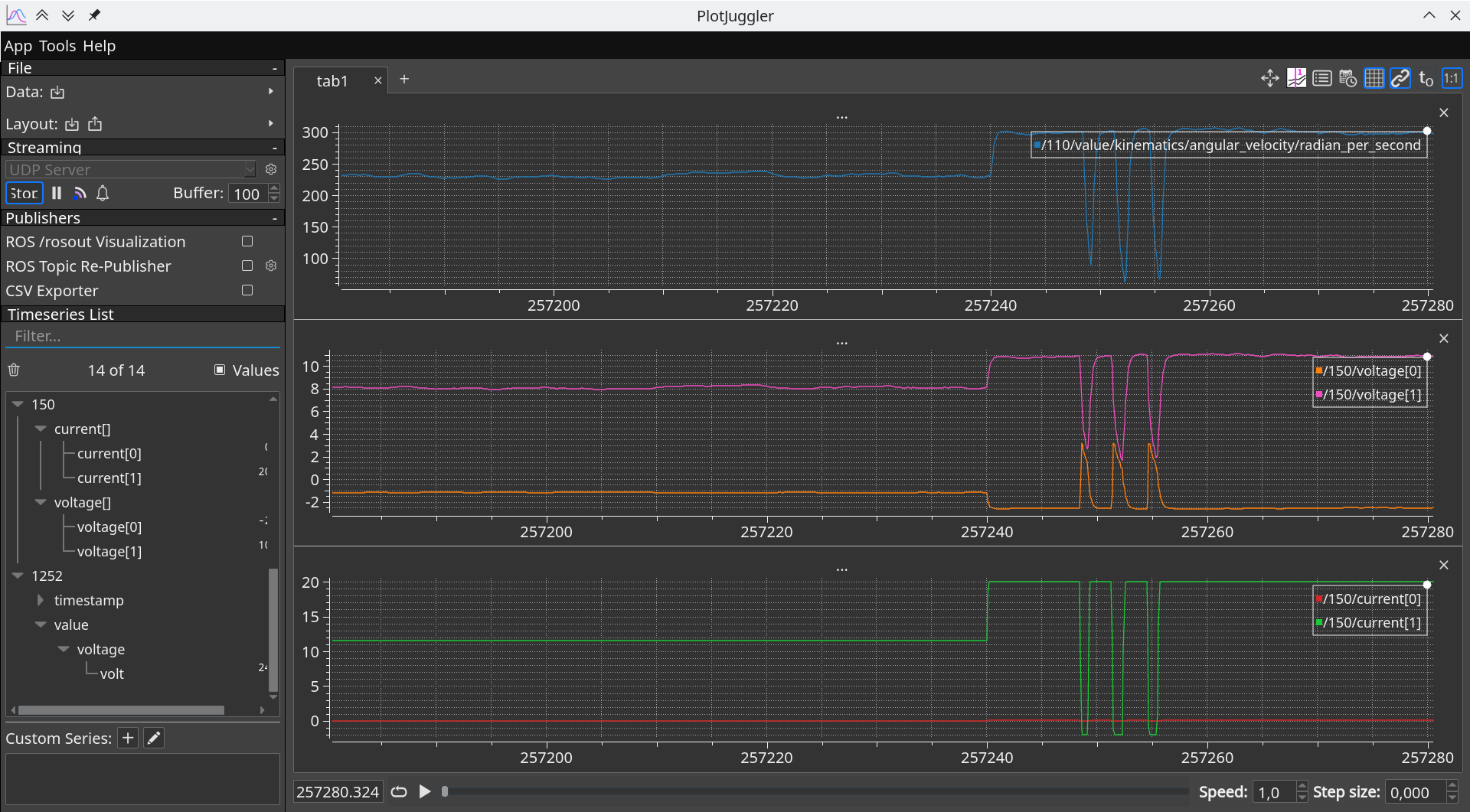
Plotting the DQ-frame current and voltage vectors using Yakut➔JSON➔UDP➔PlotJuggler.#
temperature#
Definition of zubax.telega.Temperatures.1.0;
extent 64 bytes:
1# Temperatures of key components of the drive.
2
3float16 motor           # [kelvin] NaN if thermistor is not configured
4float16 power_stage     # [kelvin]
5float16 cpu             # [kelvin]
6
7@extent 64 * 8
The motor temperature is only available if the motor temperature sensor is configured, otherwise it is set to NaN.
The power stage temperature is sampled from the VSI temperature sensor.
Subscriptions#
Topic name |
Type |
Transfer-ID timeout |
Description |
|---|---|---|---|
|
During PnP node-ID allocation; see on Nunaweb |
||
|
|
||
|
|
3 ms |
|
|
|
3 ms |
|
|
|
3 ms |
|
|
|
3 ms |
|
|
|
3 ms |
|
|
|
3 ms |
|
|
|
3 ms |
|
|
|
3 ms |
Important
Unused subscriptions should be disabled by setting the corresponding .id register to 65535.
readiness#
Definition of zubax.service.Readiness.1.0;
extent 1 bytes:
 1# The readiness state is used to command or report the availability status of a networked service (subsystem).
 2# This type is inherited from the original DS-015/UDRAL proposal.
 3#
 4# Any system shall have at least one readiness command subject that acts as a global power switch.
 5# Every subsystem controlled in such way would usually report its readiness status back to account for the fact that
 6# the transition between different readiness states may not be instantaneous.
 7# The readiness status reporting is done by means of the service heartbeat type that is also defined in this namespace;
 8# the service heartbeat type is a structural subtype of this type.
 9#
10#   +------------+
11#   | Controller |----------+----------------+----------------+---------...     readiness command subject
12#   +------------+          |                |                |
13#     ^   ^   ^             v                v                v
14#     |   |   |        +---------+      +---------+      +---------+
15#     |   |   |        | Service |      | Service |      | Service |    ...
16#     |   |   |        +---------+      +---------+      +---------+
17#     |   |   |             |                |                |
18#     |   |   +-------------+                |                |
19#     |   +----------------------------------+                |                 service heartbeat subjects
20#     +-------------------------------------------------------+
21#
22# In a less trivial use case there may be an arbitrary number of such readiness command subjects (local power switches)
23# controlling various systems within the vehicle (e.g., propulsion, perception sensors, communication, etc).
24#
25# The publication rate is defined on a per-service basis, but it should never be lower than 1 Hz,
26# excepting services that are in the SLEEP state, in which case it is permitted to cease all network activity.
27
28truncated uint2 value
29
30uint2 SLEEP = 0
31# The long-term state of minimal power consumption.
32# Typically, most subsystems are switched into the SLEEP mode when the vehicle is parked and powered off.
33# Subsystems that do not support the SLEEP state should treat it as an equivalent of STANDBY.
34#
35# A subsystem may require a substantial amount of time to exit the sleep mode (for example, time may be needed to
36# boot the operating system and run the self test procedures).
37#
38# While in the SLEEP mode, the subsystem is allowed to cease service provision and stop all network activity
39# regardless of other requirements, except that it shall be able to reactivate itself if a Readiness message is
40# received commanding any state other than SLEEP.
41
42# Value 1 is invalid and shall never be commanded.
43# Implementations receiving this value should interpret it either as SLEEP or STANDBY.
44
45uint2 STANDBY = 2
46# The state of being ready to enter the normal operating mode in a short order.
47# A subsystem that is in STANDBY state should be able to participate in the normal network activity.
48# This is the default state that the subsystem should reside in after power-on until explicitly commanded otherwise.
49
50uint2 ENGAGED = 3
51# When ENGAGED, the subsystem is performing its main intended function at the nominal performance characteristics.
52# A subsystem may require a short amount of time, possibly under a few seconds, to switch between the ENGAGED and
53# STANDBY states (in any direction).
54# Some subsystems may not differentiate between STANDBY and ENGAGED (e.g., offboard communication hardware).
55# The subsystem may disengage itself autonomously in the event of a fatal malfunction, in which case
56# the reported service health status should be WARNING.
57
58@sealed
The readiness subscription is an optional safety feature that can be enabled
to prevent accidental arming of the drive.
If the readiness subscription is configured (that is, the subject-ID is set to any valid value),
no drive command will be acted upon unless the ENGAGED readiness command is published.
If the readiness subscription is not configured, published commands are accepted immediately. Deactivation takes place upon expiration of the deadman timeout.
The Cyphal interface will automatically issue a standby command if the current state is
fault and
the readiness state transitions from any other state to engaged,
thus automatically resetting (unlatching) the fault state when the motor is started.
If the readiness subscription is not configured,
transition to the engaged state is performed upon the update of any setpoint_-subscription.
setpoint_dynamics#
See setpoint_dynamics.
setpoint_velocity#
See setpoint_velocity.
setpoint_rat_torque#
See setpoint_rat_torque.
setpoint_rat_torque_u9#
setpoint_rat_voltage#
See setpoint_rat_voltage.
setpoint_rat_voltage_u9#
setpoint_rat_velocity_u9#
This subject implements the ratiometric velocity control by multiplying the ratiometric value by
mns.ratiometric_to_absolute_mul and then forwarding the result to the velocity controller.
If the ratiometric-to-absolute multiplier is not configured, setpoints received over this subject will be ignored.
See setpoint_velocity for further details.
setpoint_servo#
See setpoint_servo.
RPC servers#
RPC-service name |
Type |
Description |
|---|---|---|
|
See on Nunaweb |
|
|
See on Nunaweb |
|
|
See on Nunaweb |
|
|
See on Nunaweb |
|
|
|
Not for production use. |
uavcan.node.GetInfo#
The node name is reported as com.zubax.telega.
The software version number indicates the version of Telega.
The minor hardware version number indicates which device Telega is running on; its values are specified in the device-specific documentation.
uavcan.node.ExecuteCommand#
The list of supported commands is provided below. If the parameter description is empty, the command does not accept one.
Command |
Parameter |
Description |
|---|---|---|
0 |
Cancel the current command; see Standby |
|
1 |
Commence Self test |
|
2 |
Commence Motor identification |
|
|
Alias for |
|
|
Execute shutdown to restart |
|
|
Firmware image file name |
Execute shutdown then launch the bootloader |
|
Reset configuration parameters to the factory defaults at next shutdown |
|
|
Shut down and lock the VSI at the hardware level immediately (restart to recover) |
Definition of uavcan.node.ExecuteCommand.1.1;
extent 300 / 48 bytes:
 1# Instructs the server node to execute or commence execution of a simple predefined command.
 2# All standard commands are optional; i.e., not guaranteed to be supported by all nodes.
 3
 4uint16 command
 5# Standard pre-defined commands are at the top of the range (defined below).
 6# Vendors can define arbitrary, vendor-specific commands in the bottom part of the range (starting from zero).
 7# Vendor-specific commands shall not use identifiers above 32767.
 8
 9uint16 COMMAND_RESTART = 65535
10# Reboot the node.
11# Note that some standard commands may or may not require a restart in order to take effect; e.g., factory reset.
12
13uint16 COMMAND_POWER_OFF = 65534
14# Shut down the node; further access will not be possible until the power is turned back on.
15
16uint16 COMMAND_BEGIN_SOFTWARE_UPDATE = 65533
17# Begin the software update process using uavcan.file.Read. This command makes use of the "parameter" field below.
18# The parameter contains the path to the new software image file to be downloaded by the server from the client
19# using the standard service uavcan.file.Read. Observe that this operation swaps the roles of the client and
20# the server.
21#
22# Upon reception of this command, the server (updatee) will evaluate whether it is possible to begin the
23# software update process. If that is deemed impossible, the command will be rejected with one of the
24# error codes defined in the response section of this definition (e.g., BAD_STATE if the node is currently
25# on-duty and a sudden interruption of its activities is considered unsafe, and so on).
26# If an update process is already underway, the updatee should abort the process and restart with the new file,
27# unless the updatee can determine that the specified file is the same file that is already being downloaded,
28# in which case it is allowed to respond SUCCESS and continue the old update process.
29# If there are no other conditions precluding the requested update, the updatee will return a SUCCESS and
30# initiate the file transfer process by invoking the standard service uavcan.file.Read repeatedly until the file
31# is transferred fully (please refer to the documentation for that data type for more information about its usage).
32#
33# While the software is being updated, the updatee should set its mode (the field "mode" in uavcan.node.Heartbeat)
34# to MODE_SOFTWARE_UPDATE. Please refer to the documentation for uavcan.node.Heartbeat for more information.
35#
36# It is recognized that most systems will have to interrupt their normal services to perform the software update
37# (unless some form of software hot swapping is implemented, as is the case in some high-availability systems).
38#
39# Microcontrollers that are requested to update their firmware may need to stop execution of their current firmware
40# and start the embedded bootloader (although other approaches are possible as well). In that case,
41# while the embedded bootloader is running, the mode reported via the message uavcan.node.Heartbeat should be
42# MODE_SOFTWARE_UPDATE as long as the bootloader is runing, even if no update-related activities
43# are currently underway. For example, if the update process failed and the bootloader cannot load the software,
44# the same mode MODE_SOFTWARE_UPDATE will be reported.
45# It is also recognized that in a microcontroller setting, the application that served the update request will have
46# to pass the update-related metadata (such as the node-ID of the server and the firmware image file path) to
47# the embedded bootloader. The tactics of that transaction lie outside of the scope of this specification.
48
49uint16 COMMAND_FACTORY_RESET = 65532
50# Return the node's configuration back to the factory default settings (may require restart).
51# Due to the uncertainty whether a restart is required, generic interfaces should always force a restart.
52
53uint16 COMMAND_EMERGENCY_STOP = 65531
54# Cease activities immediately, enter a safe state until restarted.
55# Further operation may no longer be possible until a restart command is executed.
56
57uint16 COMMAND_STORE_PERSISTENT_STATES = 65530
58# This command instructs the node to store the current configuration parameter values and other persistent states
59# to the non-volatile storage. Nodes are allowed to manage persistent states automatically, obviating the need for
60# this command by committing all such data to the non-volatile memory automatically as necessary. However, some
61# nodes may lack this functionality, in which case this parameter should be used. Generic interfaces should always
62# invoke this command in order to ensure that the data is stored even if the node doesn't implement automatic
63# persistence management.
64
65uint8[<=uavcan.file.Path.2.0.MAX_LENGTH] parameter
66# A string parameter supplied to the command. The format and interpretation is command-specific.
67# The standard commands do not use this field (ignore it), excepting the following:
68#   - COMMAND_BEGIN_SOFTWARE_UPDATE
69
70@extent 300 * 8
71
72---
73
74uint8 STATUS_SUCCESS        = 0     # Started or executed successfully
75uint8 STATUS_FAILURE        = 1     # Could not start or the desired outcome could not be reached
76uint8 STATUS_NOT_AUTHORIZED = 2     # Denied due to lack of authorization
77uint8 STATUS_BAD_COMMAND    = 3     # The requested command is not known or not supported
78uint8 STATUS_BAD_PARAMETER  = 4     # The supplied parameter cannot be used with the selected command
79uint8 STATUS_BAD_STATE      = 5     # The current state of the node does not permit execution of this command
80uint8 STATUS_INTERNAL_ERROR = 6     # The operation should have succeeded but an unexpected failure occurred
81uint8 status
82# The result of the request.
83
84@extent 48 * 8
low_level_io#
Not for production use.
Transports#
Some Telega-based products may supply power through the network ports.
This behavior is controlled via the aux.power_output register.
Cyphal/CAN#
Telega supports the Classic CAN bus interface, which may be doubly-redundant depending on the hardware configuration. The primary interface is labeled CAN1 and the redundant, if available, is labeled CAN2.
If the CAN bus interface is not used in a given application, register uavcan.can.count should be set to zero.
Beware that once this is done, the device will no longer be possible to contact via Cyphal/CAN;
hence, if Cyphal/CAN is the only network interface available on the device, this rule does not apply.
“On CAN bus topology and termination” provides recommendations on the usage of CAN bus in relevant applications.
Redundancy#
If a redundant CAN interface is available but only one is used:
The used interface shall be strictly CAN1.
Register
uavcan.can.countshall be set to 1, thereby disabling CAN2.
The default value of uavcan.can.count depends on the capabilities of the hardware.
The register should always be set explicitly when the device is commissioned to ensure that
the configuration meets the requirements of the application.
Activity indication via LED#
Telega-based devices equipped with Cyphal/CAN may provide a dedicated LED indicator per interface. Said indicator illuminates briefly per CAN frame either successfully received or successfully transmitted by the device via this interface. Incoming frames that are rejected by the CAN acceptance filters do not cause the LED to illuminate.
Bitrate#
The CAN bitrate is configured via register uavcan.can.bitrate,
where the first value sets the bitrate and the second value is ignored.
If the configured bitrate is not supported, Telega will automatically revert to the default value.
Telega does not support automatic CAN bitrate detection.
Cyphal/UDP#
Coming soon. With a multi-drop-capable deterministic 10BASE-T1S PHY, this interface is expected to be a superior alternative to CAN FD in high-performance systems.