Yakut CLI tool#
This tutorial demonstrates how to configure and evaluate Telega-based drives in the lab using the Yakut CLI tool. The tutorial is mostly intended for GNU/Linux and macOS; for Windows, minor adjustments may be needed.
Yakut is well-suited for building automation scripts, which makes this tutorial a good starting point for developing automation solutions such as testing and/or configuration scripts for mass production of vehicles or other products involving Telega-based motor controllers.
The tutorial is written on the assumption that the hardware is arranged roughly as follows: a Telega-based motor controller is connected to a motor installed on the Zubax Heidy test stand; a Telega-based motor control module is installed into a custom power stage and connected to the opposite motor on the test stand. Both devices are powered from the same DC power supply and reside on the same network which is also connected to your PC.
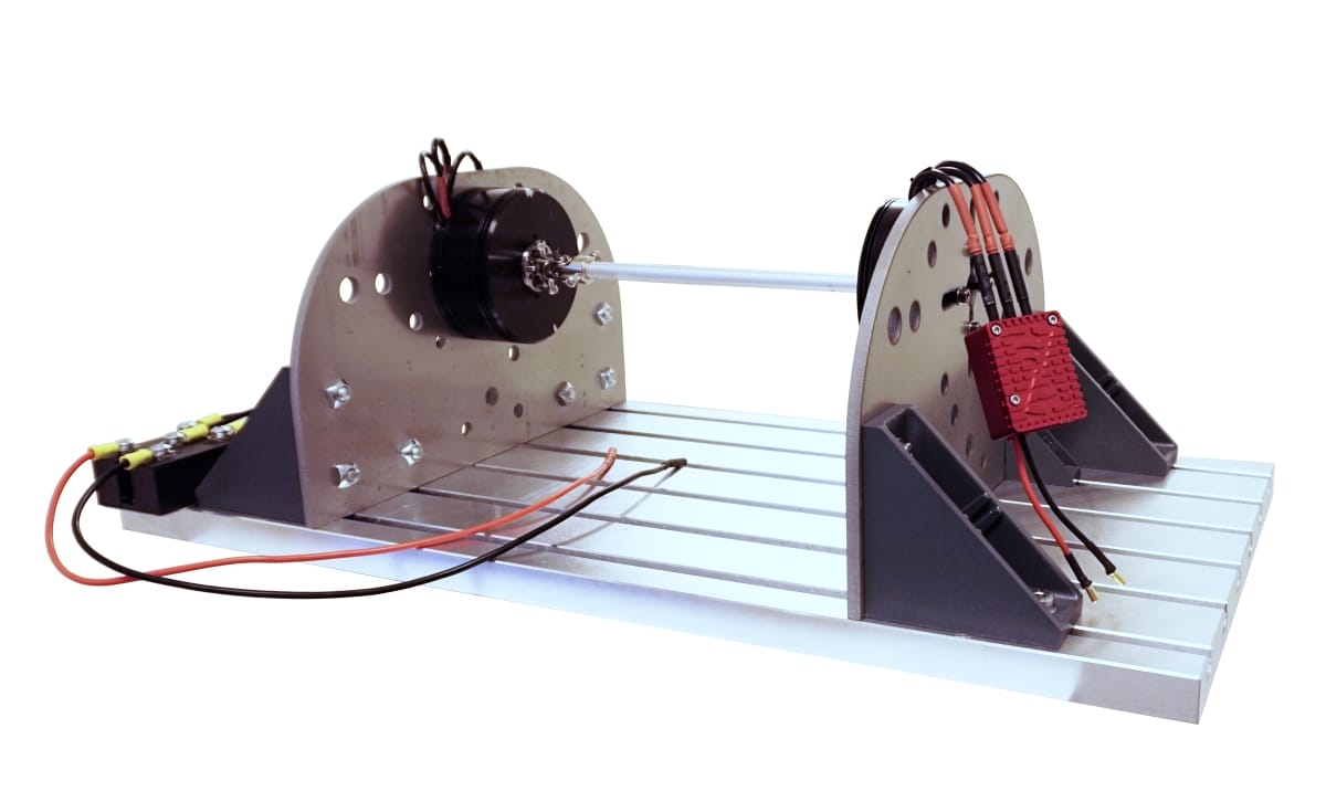
The Zubax Heidy test stand with two motors connected to each other. Each motor is driven by its own Telega-based motor controller; both controllers are connected to the same network.#
Your hardware setup is not required to exactly match the description. You can still follow along, slightly adjusting the instructions as necessary to match your setup.
Prerequisites#
At least one Telega-based motor controller.
A motor per motor controller (unless it is part of an integrated drive).
A DC power supply. The power supply should support regenerative braking, or there should be a large (ca. 100 mF) capacitor attached to its output, or there needs to be an electronic load connected in parallel to absorb energy recovered during braking.
A network interface adapter, such as Zubax Babel.
The following software installed on your computer:
Recommended equipment:
An electric motor test bench, such as Zubax Heidy, a propeller stand, or an equivalent rig depending on the intended application.
Connect the devices#
Connect the controllers to the network and power them up. The RGB LED will start blinking. In the case of a motor controller or an integrated drive, the LED will blink green, indicating that the device is in the standby mode. In the case of a controller based on a motor control module (like Mitochondrik LV), the LED may be blinking red-yellow, indicating that the inverter parameters are not set (unless they are) and the device remains in the uninitialized state.
Ensure the motors are connected.
Set up Yakut#
Install Yakut on your computer following the installation instructions provided in its documentation.
Install the zubax vendor-specific DSDL namespace as well
(simply download the archive and extract it into your ~/.cyphal directory for Yakut to see it;
directory ~/.cyphal/zubax/ should exist).
Before proceeding, we will need to ensure that Yakut is able to access the network. The specific instructions depend on the OS and the shell used. Once Yakut is set up, the subsequent steps will be mostly the same regardless of the OS.
If you are using CAN bus, then the bit rate shall be set to 1 Mbps during the initial configuration,
as this is the default bit rate for Telega-based motor controllers.
It can be changed afterward via uavcan.can.bitrate.
GNU/Linux or macOS with sh/bash/zsh#
If you are using Cyphal/CAN with an SLCAN-compatible USB-CAN adapter,
such as Zubax Babel,
paste the following snippet into a file named env_slcan.sh:
 1if ! [ -e /sys/class/net/slcan0 ]; then
 2    # Install this script to your PATH: https://gist.github.com/pavel-kirienko/32e395683e8b7f49e71413aebf5e1a89
 3    sudo setup_slcan -r /dev/serial/by-id/usb-Zubax*Babel*
 4fi
 5export UAVCAN__CAN__IFACE='socketcan:slcan0'
 6if [ -e /sys/class/net/slcan1 ]; then
 7    export UAVCAN__CAN__IFACE="$UAVCAN__CAN__IFACE socketcan:slcan1"
 8fi
 9export UAVCAN__CAN__MTU=8
10export UAVCAN__CAN__BITRATE='1000000 1000000'   # Arbitration and data segment bit rates.
11export UAVCAN__NODE__ID=$(yakut accommodate)    # Pick a node-ID for Yakut automatically.
12echo "Auto-selected node-ID for this session: $UAVCAN__NODE__ID"
Then source the file into your shell session as follows:
1. env_slcan.sh
Sourcing, as opposed to execution, will make the current shell session ingest the environment variables defined in the file. Whenever you start a new shell session for use with Yakut, be sure to always source this file first.
You can have several env_*.sh files for different network configurations that you use often.
People familiar with languages like Python will find it somewhat analogous to virtual environments.
If you get an error from Yakut that goes along the lines of the transport not being configured, that likely means that you forgot to source the environment file.
Windows with PowerShell#
If you are using Cyphal/CAN with an SLCAN-compatible USB-CAN adapter,
such as Zubax Babel,
paste the following snippet into a file named env_slcan.ps1:
$env:UAVCAN__CAN__IFACE="slcan:COM4"          # Specify the correct port number here.
$env:UAVCAN__CAN__MTU="8"
$env:UAVCAN__CAN__BITRATE="1000000 1000000"   # Arbitration and data segment bit rates.
$env:UAVCAN__NODE__ID=yakut accommodate       # Pick a node-ID for Yakut automatically.
echo "Auto-selected node-ID for this session: $env:UAVCAN__NODE__ID"
Then source the file into your shell session as follows:
1. env_slcan.ps1
Same sourcing considerations apply.
Update the firmware#
You are free to skip this section if you don’t need to update the Telega firmware.
If you do, browse over to https://files.zubax.com/products/com.zubax.telega and fetch the binary you need,
then invoke the file-server command as follows,
pointing it to the directory that contains the downloaded .bin file:
y --verbose file-server --plug-and-play allocation_table.db /your/download/folder/ --update-software
Warning
The firmware update can only succeed if the device is connected to the network via the first interface rather than its redundant pair; for example, CAN1 or Eth1 but not CAN2 or Eth2. If this condition is not met, the file server will keep restarting the device continuously. See Embedded bootloader.
The devices will be restarted when the update is finished.
The progress can be monitored via the LED or by watching the output of the Yakut monitor command.
Remove --verbose if the command produces too much output for your taste.
Configure the Cyphal stack#
A Cyphal node has to have a unique node-ID assigned to be reachable over the network. By default, Telega-based motor controllers come with an unset node-ID, which triggers the motor controller to obtain one automatically following the plug-and-play (PnP) node-ID allocation procedure (analogous to DHCP in IP networks). For the procedure to succeed, we launch the Yakut monitor command in the PnP mode (the file name specifies where the allocation table will be stored, it can be arbitrary):
1y mon --plug-and-play allocation_table.db
The allocation takes a few seconds. Once completed, the monitor may present roughly the following picture; in this case we see that the allocated node-IDs are 124 and 125 (they may be different in your case):
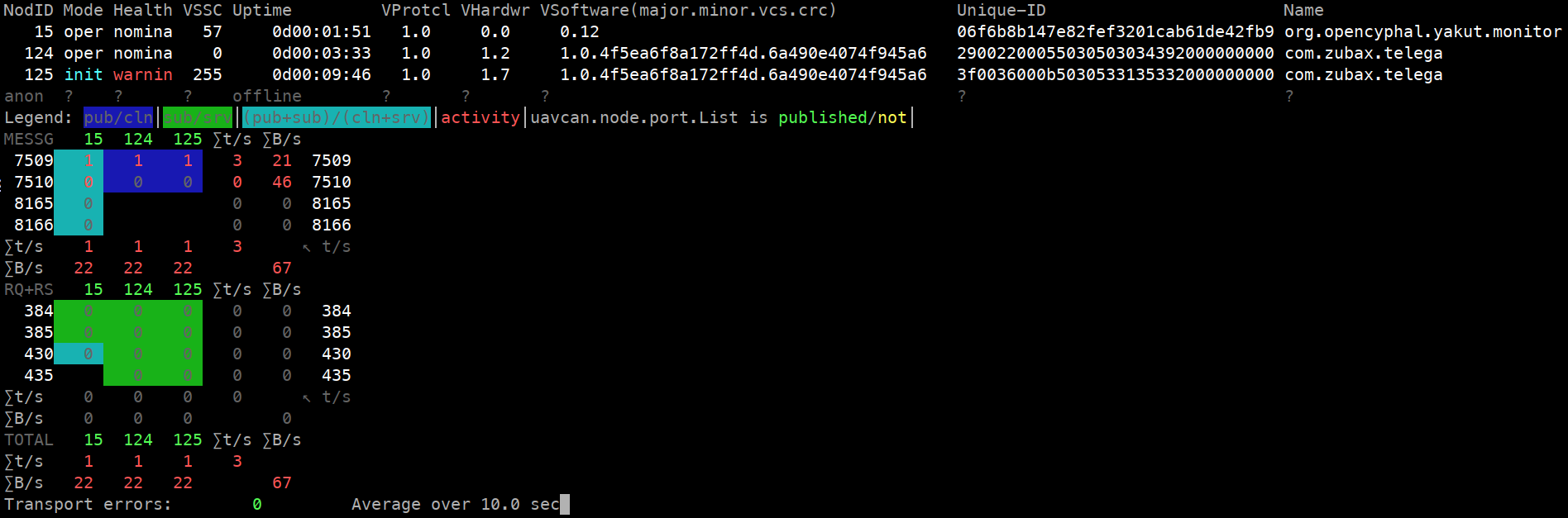
It is visible that node 124 — the motor controller — is in the standby state; while node 125 — the motor control module — is unable to enter the normal operating mode due to missing VSI parameters, which we will address later.
The devices are now fully reachable via Cyphal. They can be restarted to save the allocated node-ID so that the PnP allocator is not needed next time, but it can be done later as well:
1y cmd 124-126 re
Notice how we use 124-126 here to specify that we want to apply the command to nodes 124 and 125
(the upper bound is not inclusive).
We could also say 124,125 instead of 124-126 to the same effect.
The same holds for other commands which can operate on multiple nodes at once.
Learn to read and write configuration registers#
The devices are already reachable over the network, but they must be configured further before they are ready for use.
This is done by changing the configuration registers, which are just named values.
To get a feel of what they are, run the register-list command, or rl,
to see the list of register names available per node:
y rl 124,125 # Hint: you can pipe the output to jq for syntax highlighting
Some of these are configuration parameters (such registers are called “mutable persistent”), others are diagnostic values computed upon access (like the stack usage or system status).
If you run the command with just one node-ID given, it will not be included in the output; the rationale is that since there is just one node-ID, providing it in the output would be redundant as there is no ambiguity either way:
y rl 124 # The output is just a list of names without the node-ID: [...]
This is sometimes undesirable — more on this later. You can force the node-ID to always appear in the output by using a set of one node-ID rather than the node-ID alone; this is done by adding a comma at the end:
y rl 124, # Same result except that the output is now a dict: {124: [...]}
You will notice that the same principle is used in some other commands.
As a diligent reader, you might be wondering at this point what use all this information about Yakut is, if one simply wants to configure some motor controllers? To quote Terry Pratchett, “Build a man a fire, and he’ll be warm for a day. Set a man on fire, and he’ll be warm for the rest of his life.” At the end of this endeavor, you are expected to be proficient enough with Yakut to deserve a new entry in your LinkedIn skillset list.
Just the names are not enough, we also need the values.
Those can be accessed individually if you want to see a specific register alone using the register command, or r:
y r 124,125 sys.status # Prints a dict of values, where keys are node-IDs (124 and 125 in this case)
This is helpful for interactive use but if you want to fully configure a device, let alone several,
it is more convenient to use the register-batch command, or rb.
It can be used to mass read and write registers across an arbitrary number of nodes.
The register-batch command accepts YAML/JSON document via stdin that contains the list of registers to read,
like ["foo.bar", "baz.qux"],
or a dict of lists per node-ID, like {124: ["foo.bar", "baz.qux"], 125: ["zoo.boo"]}.
If registers need to be written, then the lists are replaced with dicts.
If the input document does not contain the node-IDs,
they will have to be provided explicitly as a command line argument;
as will be shown below, this is an important feature for deploying configuration files across multiple nodes.
Conspicuously, the output format of register-list matches the input format of register-batch,
so we can pipe the output of one to the other:
y rl 124,125 | y rb # Read the register names, then read their values.
The above reads the same list of registers twice as it is identical (or mostly identical) on both nodes.
One could achieve the same effect by reading the list only once such that the output of the register-list command
does not include the node-ID, and then provide the node-IDs explicitly as an argument:
y rl 124 | y rb 124,125 # Read the register names from 124, then read their values from 124 and 125.
If some registers happen to be missing, the tool will issue a warning and the corresponding values will be set to
null in the output document.
This may happen for nodes that reside in the uninitialized state,
which we will address soon.
The main reason for doing this is to store the configuration into a file that can be edited later on.
To do this, pipe the output of the register-batch command into a file,
which can be JSON or YAML (YAML is much more human-friendly so it’s best to use that).
One last thing to note is that we only want the configuration registers to end up in the file,
so we ask the command to remove all other registers from the output by passing the option
--only=mp (where “mp” stands for “mutable persistent”):
y rl 124 | y --yaml rb 124,125 --only=mp > configuration.yaml
#              ^^^^-force YAML   ^^^^^^^-only mutable persistent
We now have configuration.yaml which needs to be edited.
Prepare the configuration file#
Fire up your favorite text editor (preferably with YAML syntax highlighting) and edit out the stuff you don’t need.
For maximum repeatability, it is possible to keep all the parameters in the configuration file
so that any device can be brought to a known configuration by merely deploying the full configuration file on it
without the need to perform a factory reset first.
Beware though that minor releases of Telega may add new parameters, or remove existing ones
(the register-batch command will politely notify you of the latter circumstance).
The main parameters to focus on are the motor characteristics registers motor.*
and the Cyphal stack registers uavcan.*
(named so for historical reasons).
For motor control modules (node 125 in our case), the vsi.* parameters need to be set as well
(for complete motor controllers and integrated drives, these are already set correctly out of the box,
just be sure not to overwrite them accidentally).
You will likely want to alter the command-specific registers as well, such as drive.*,
depending on your application.
If you have a dozen or more motor controllers on the network with auto-allocated node-ID values,
you may be wondering how to identify which is which.
One way to know is to restart them one by one and take note of which one is affected
by watching its LED intently: y cmd 125 restart.
You can also reassign the auto-allocated node-ID values if desired (e.g., for semantic grouping) like so:
y r 125 uavcan.node.id 100 (and then restart).
For the purposes of this demo, we end up with the edited file as follows:
# This device will be used with the generator on the test stand.
124:
  # DRIVE task: common parameters.
  drive.current_brake_pu:                   0.3
  # DRIVE task: run strategy.
  drive.runner.type:                        1             # Use the passive spinup run strategy.
  drive.runner.1_passive.velocity_off_on:   [5.0, 10.0]
  # Motor parameters. The motor used here is T-Motor P80II KV120.
  motor.current_max:                        50
  motor.mechanical_ratio:                   21            # The rotor has 42 poles and there is no gearbox, hence 21.
  motor.flux_linkage:                       0.0
  motor.inductance_dq:                      [0.0, 0.0]
  motor.resistance:                         0.0
  motor.current_ramp:                       5000          # From the application requirements.
  # Cyphal/CAN parameters.
  uavcan.can.bitrate:                       [1000000, 0]
  uavcan.can.count:                         1             # In this setup we are not using CAN2.
  # Cyphal ports.
  uavcan.pub.dq.id:                         1000
  uavcan.pub.dynamics.id:                   1001
  uavcan.pub.power.id:                      1002
  uavcan.sub.setpoint_rat_torque.id:        1100
  # General parameters.
  sys.debug:                                false         # Debug interfaces shall be disabled in production use.

# This device will be used to drive the other motor.
125:
  # DRIVE task: run strategy.
  drive.runner.0_ramp.velocity_stall_spinup: [5, 20]
  # DRIVE task: velocity controller (ignore if velocity control is unnecessary).
  drive.velocity_ctl.2_indi.acceleration_pi: [50, 0]
  drive.velocity_ctl.2_indi.mass:           1.0e-5        # Use best guess if unknown.
  drive.velocity_ctl.type:                  2
  # Motor parameters. The motor used here is SunnySky X8016S KV120.
  motor.current_max:                        60
  motor.mechanical_ratio:                   14            # The rotor has 28 poles and there is no gearbox, hence 14.
  motor.flux_linkage:                       0.0
  motor.inductance_dq:                      [0.0, 0.0]
  motor.resistance:                         0.0
  motor.current_ramp:                       5000          # From the application requirements.
  motor.thermistor_v2k:                     [104.47, 71.43, 54.99]  # KTY84 with 1.2k pull-up to 3.3V.
  # Voltage source inverter (VSI) parameters (only for motor control modules).
  # This device is a motor control module so this information needs to be given explicitly.
  # The other device is a motor controller so it already knows the correct settings for the VSI.
  vsi.bridge_resistance:                    [0.002, 0.003, 0.002, 0.003, 0.002, 0.002]
  vsi.dc_voltage_gain:                      18.8
  vsi.phase_current_gain:                   [100, 100,  25,  25]
  vsi.phase_current_stderr:                 [0.3, 0.3, 0.2, 0.2]
  vsi.thermistor_v2k:                       [223.15, 100.0, 0.0]
  # Cyphal/CAN parameters.
  uavcan.can.bitrate:                       [1000000, 0]
  uavcan.can.count:                         1             # In this setup we are not using CAN2.
  # Cyphal ports.
  uavcan.pub.dq.id:                         1010
  uavcan.pub.dynamics.id:                   1011
  uavcan.pub.power.id:                      1012
  uavcan.pub.temperature.id:                1013
  uavcan.sub.setpoint_rat_torque.id:        1101
  uavcan.sub.setpoint_velocity.id:          1102
  # Aux I/O pin.
  aux.pull:                                 1             # Enable pull-up for the motor thermistor.
  # General parameters.
  sys.debug:                                false         # Debug interfaces shall be disabled in production use.
In this example, we configure the velocity control mode with the INDI controller, which requires the moment of inertia to be known. You can safely omit this if your application does not require the velocity control mode, or use a different velocity control strategy if your load does not have a well-defined constant moment of inertia. More on this in the drive command documentation.
You may notice that the key motor parameters are missing: the flux linkage, inductance, etc. For the sake of making this example more interesting, we will assume that these values are unknown. You are encouraged, however, to check if your motor(s) are listed in the PMSM parameters spreadsheet, and if so, simply copy the known values from there into your configuration file and then possibly skip the next section.
Before proceeding, we need to deploy the configuration that we just created to the network and restart the devices so that the changes take effect:
y rb < configuration.yaml
y cmd 124-126 restart       # Restarting will commit all configuration to the non-volatile memory.
A few seconds later, the monitor command introduced earlier will present roughly the following:
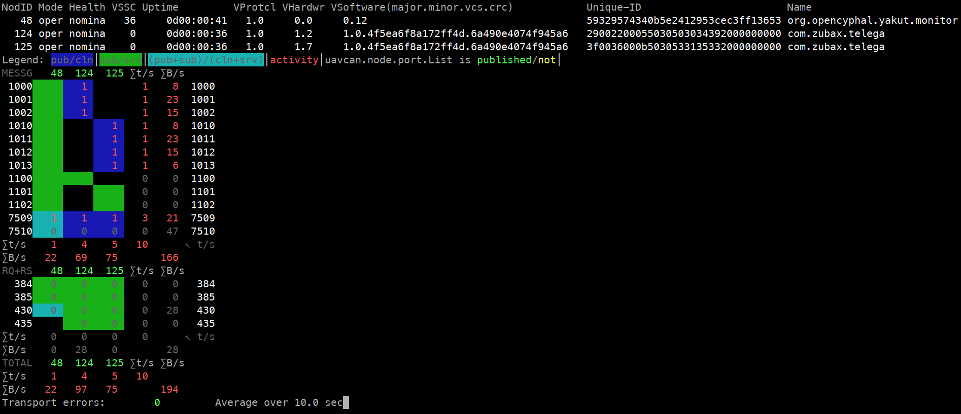
Observe that the connectivity matrix now looks different, according to the configuration we set in the YAML file.
One usage pattern that you should know about is to extract some node-agnostic parameters into configuration files
that are not keyed by node-ID.
As we know from the previous section,
the powerful register-batch command can accept a dict of dicts like {125: {REGISTER: VALUE, ...}}
and also simply a flat dict of register values like {REGISTER: VALUE, ...}.
In the latter case, it delays the node-ID specification to the point of the command invocation,
as it is not specified in the file.
This means that you can extract common configuration into flat files like this (just an example):
# shared.yaml
uavcan.can.bitrate:                       [1000000, 0]
uavcan.can.count:                         1
sys.debug:                                false
And then distribute it to several nodes:
y rb 124-126 < shared.yaml
y cmd 124-126 restart
Run the motor identification#
If the motor parameters are not known from the motor datasheet nor elsewhere, and the motor is not listed in the Zubax PMSM database, the motor identification procedure will have to be executed. If this does not apply in your case, feel free to skip this section.
Before running the motor identification procedure, it is important to ensure that the motor shaft is disconnected from any significant load. For instance, if the motor is directly attached to the thruster of a watercraft, merely pulling the thruster out of the water should be enough. If the motor is attached to a gearbox or a large fan, it is strongly advised to disconnect it beforehand to ensure that the load does not interfere with the motor parameter measurement. If the motor is connected to another one on a test stand, they must be mechanically decoupled. If none of that is possible, different methods of motor identification will have to be resorted to, which are covered in a separate tutorial.
Having disconnected the load from the shaft, we are now good to commence the identification procedure. It is critical that we have completed the initial configuration beforehand, as the basic motor parameters such as the maximum current should be set before identification is executed; the VSI parameters are also required.
To begin the process, invoke the vendor-specific command 2:
y cmd 124-126 2
Feel free to fire up the monitor again and watch it at your leisure while Telega does the work. You will see that the node mode has changed to “maintenance”, and it will remain in this state until the process is finished. Upon completion, the next state will be standby in case of success, or fault in case of fault. The status can also be monitored by reading the JSON-formatted system status register:
y r 124-126 sys.status
When finished, you can inspect the results and copy the values into your configuration file for future reference:
$ y r 124-126 motor.resistance
{124: 0.02878352627158165, 125: 0.01696169748902321}

$ y r 124-126 motor.inductance_dq
124: [1.4745361113455147e-05, 1.4745361113455147e-05]
125: [1.6833639165270142e-05, 1.6833639165270142e-05]

$ y r 124-126 motor.flux_linkage
{124: 0.002564611379057169, 125: 0.0032328388188034296}
Do not forget to restart the node to commit the new values into the non-volatile memory (no need to re-deploy the configuration file as the registers are already updated with the measured values):
y cmd 124-126 restart
Run the motor#
Both controllers are now ready to work. Yakut monitor should inform you that both of them reside in the nominal operational state. We proceed by starting the motor in the ratiometric torque control mode at 0.05 of the maximum:
y pub -T0.1 1101:uavcan.primitive.scalar.real16 0.05
#           ^^^^-this number comes from the YAML file we wrote earlier. It can be arbitrary.
Notice how we set the publication period to a lower value than the default of 1 second. Otherwise, the drive would fail to start as the deadman timeout would expire before the arrival of the next command.
The motor may spin up quite rapidly or not at all depending on the load. If the load torque exceeds the torque setpoint, the motor may fail to spinup or stall shortly afterwards. As an example, try this to see how it manifests in your case:
y pub -T0.1 1101:uavcan.primitive.scalar.real16 1.0e-6 # A very low torque setpoint.
Next, we try the velocity control mode with the setpoint of 50 radian/second (Cyphal and Telega use SI throughout because unit inconsistency is risk-wise unjustifiable[1][2]):
y pub -T0.1 1102:uavcan.primitive.scalar.real16 50
If the motor fails to start or spins up briefly and then stops again,
check that you have configured the velocity controller,
and that the drive.velocity_ctl.type register is set correctly.
Leave the motor spinning and subscribe to some diagnostic topics meanwhile:
y sub 1011:zubax.physics.dynamics.DoF3rdTs 1012:zubax.physics.electricity.PowerTs --sync --redraw
You can export the data into a JSON file for a later analysis (e.g., in Jupyter):
y sub 1011:zubax.physics.dynamics.DoF3rdTs 1012:zubax.physics.electricity.PowerTs --sync > data.json
Now, we fire up another terminal with similar subscriptions for the other drive (the generator) and keep it running:
y sub 1001:zubax.physics.dynamics.DoF3rdTs 1002:zubax.physics.electricity.PowerTs --sync --redraw
With the first motor running, start the other one in the ratiometric torque mode and zero setpoint (i.e., freewheeling):
y pub -T0.1 1100:uavcan.primitive.scalar.real16 0
Nothing should change, as the generator controller is commanded to not put any torque on the shaft.
You should see both subscribers, that we started earlier, display the same velocity. If the signs are opposite, swap any two phases on either motor to align the forward direction. If the signs are the same but the values differ in magnitude, the mechanical ratio setting is incorrect.
Interesting things begin to happen when you command the generator controller to apply torque in the opposite direction of the driving motor:
y pub -T0.1 1100:uavcan.primitive.scalar.real16 -- -0.3 # The "--" is to disambiguate negative number from options.
Naturally, current consumption goes up on the driving side, and on the generator side, recovered current shows up as negative; the following snippet shows both side-by-side:
1011:                                           │ 1001:
  timestamp: {microsecond: 0}                   │   timestamp: {microsecond: 0}
  value:                                        │   value:
    kinematics:                                 │     kinematics:
      base: {position: 128.117, velocity: 20.0} │       base: {position: 128.116, velocity: 20.0}
      acceleration: -0.7822689414024353         │       acceleration: -0.394528865814209
    force: 1.0244967937469482                   │     force: -1.211815357208252
1012:                                           │ 1002:
  timestamp: {microsecond: 0}                   │   timestamp: {microsecond: 0}
  value:                                        │   value:
    current: {ampere: 0.8830548524856567}       │     current: {ampere: -0.281753271818161}
    voltage: {volt: 29.993328094482422}         │     voltage: {volt: 30.123701095581055}
You can reverse the roles of the motor and generator by sending a positive torque setpoint to the generator while keeping the motor at the same velocity setpoint in the velocity control mode. In order to maintain the same set velocity while the motor is driven by an external force, the controller will have to sink power from the shaft to decelerate it, returning the excess into the DC link as negative current. One potential issue you may run into is related to the braking (regeneration) current limiting. By default, the braking (regeneration) current may be limited to some small fraction of the rated phase current. If the braking current limit is indeed low and you send a large positive torque setpoint to the generator, the torque may exceed the ability of the other side to brake due to the aforementioned limit, which will cause the system to accelerate until the DC link voltage limit is reached.
If you have a joystick, a MIDI controller, or a similar input device supported by Yakut,
you can replace the fixed arguments in the command publishers above with input expressions like '!$: "A(1,0)-A(1,1)"'
and adjust the values interactively using the joystick.
Similarly to joysticks, it is possible to generate arbitrary signals as a function of time,
like !$ "sin(t * pi * 2) * 10".
It is hard to overstate how helpful these features can be during bench testing.
This tutorial will not go into detail on this since this topic is already well-covered in the
Yakut documentation.
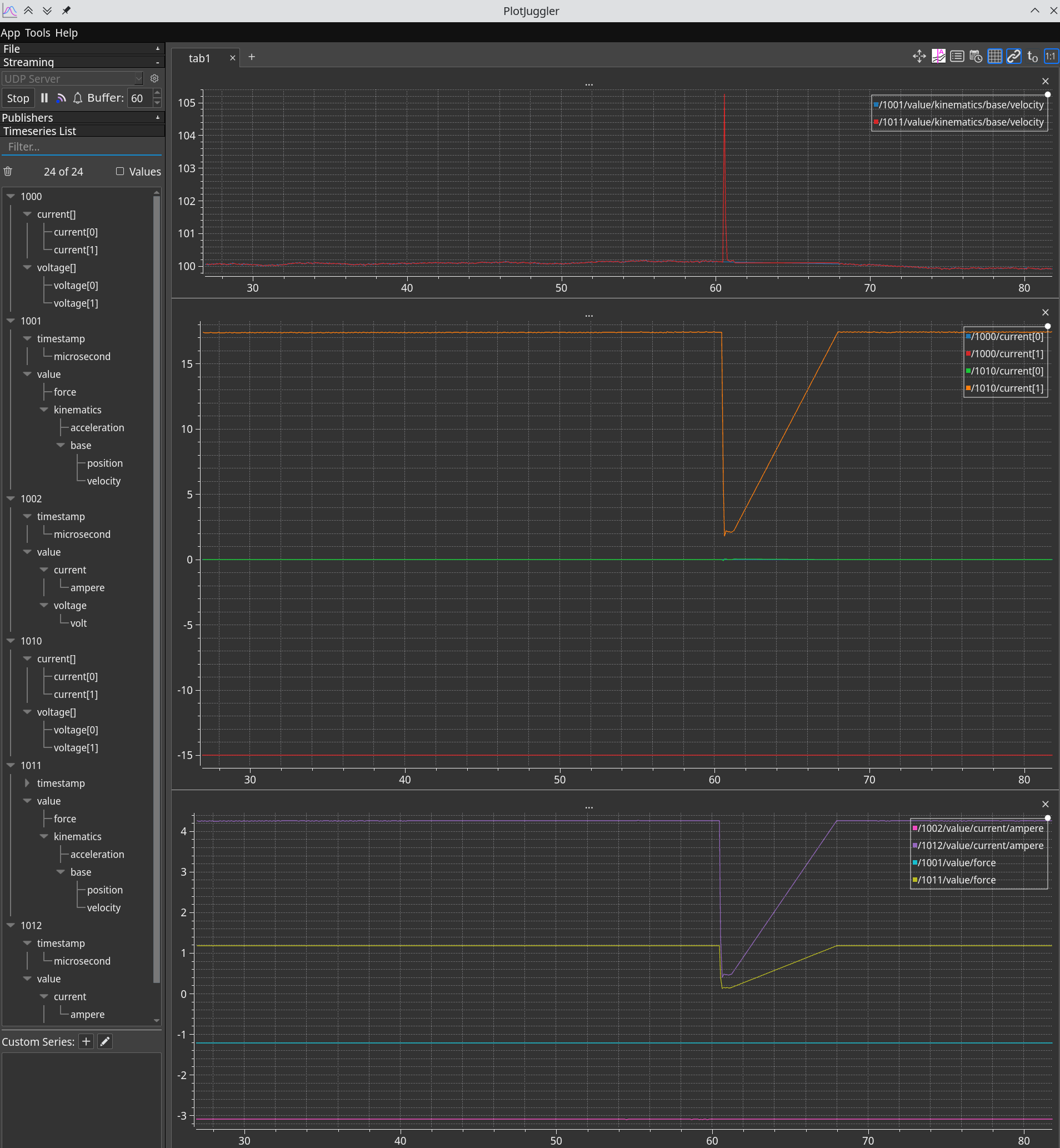
Plot data using PlotJuggler#
The text-based representations produced by Yakut may occasionally be unfit for comprehensive analysis; for that, one wants to see plots, preferably in real time. So fire up PlotJuggler and enable the UDP JSON streaming server:
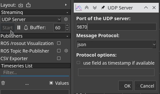
Press the OK button.#
Now pipe the output of the Yakut subscriber into netcat:
y sub 1000:zubax.telega.dq                      \
      1001:zubax.physics.dynamics.DoF3rdTs      \
      1002:zubax.physics.electricity.PowerTs    \
      1010:zubax.telega.dq                      \
      1011:zubax.physics.dynamics.DoF3rdTs      \
      1012:zubax.physics.electricity.PowerTs    \
      | nc -u localhost 9870
Note that we are not using --sync here.
You can see the effect of this option in the terminal if you compare the output of any subscription command
with and without it.
With --sync,
temporally adjacent messages from the specified topics will be emitted all at once as a single JSON/YAML document;
this is a paramount feature for many real-time applications.
Without synchronization,
each received message will be emitted as a standalone document with no regard for its neighbors.
When using PlotJuggler, --sync should not be used because:
We are subscribing to topics published to by independent nodes asynchronously, so attempting to synchronize them is futile (likely no data will be produced barring the case of spurious synchronization).
PlotJuggler is unable to make use of synchronized groups anyway.
The subscriber we launched above will format the Cyphal messages in JSON and pipe them to PlotJuggler via UDP. A few clicks later, we can get the following: